Motivation
The recent find of some good looking 3/4″ plywood was the swift kick I needed to get the ball rolling on a long dormant project. A few years ago I started down the road of building a Fender Bassman clone based on the 5F6 circuit. I was going to do this remotely with a friend. He would handle some electronics analysis for some mods we had in mind, and I would guide the mod selection and build the cabinet. I even went so far as to buy a chassis.
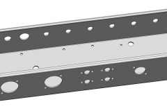
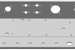
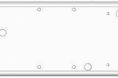
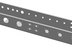
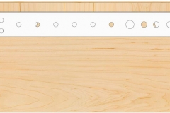
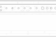
Unfortunately the project never went much further and the chassis sat in the corner of my room for a long time. Then, looking for a CAD project to practice on, I picked it up and got a sheet metal part about 80% done. It was a full box with one of the three faces completed with punched holes.
Getting Started
Knowing I had the chassis model nearly done I started to put together a model of the plywood cabinet. I’ve never had much luck modeling larger assemblies from the ground up and wanted to try something new. I had heard the term “top-down” in relation to CAD models and it seemed like the way to go.
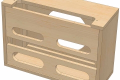
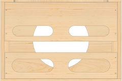
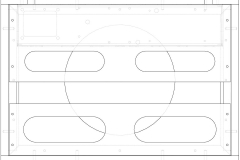
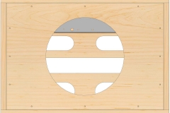
Step one was to do a little research on Fender cabinets similar to what I had in mind. I wanted to skip the 4×10 configuration the Bassman is known for in favor of a much more portable and apartment friendly 1×12 combo. I used a few pictures and drawings of the 4×10 configuration to get an idea for the parts involved, then changed the baffle design and size to fit a single 12″ speaker.
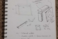
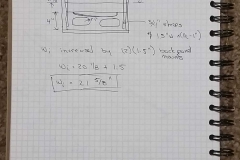
With an understanding of the parts that I would need, I then took the idea to paper to start roughing out dimensions. The big thing I’m trying to find out while doing this are the static dimensions I’m working around. I know I will have a 12″ speaker, which means the baffle will need to be large enough to support it. The chassis is already purchased, so the interior of the cabinet needs to be at least wide enough to house it.
Since this design is really about what I’m putting into the cabinet, many of the dimensions are driven by the interior spacing. This is where the CAD model will simplify my life greatly. i can create the fixed dimension pieces and dimension the pieces out from there. For example, I set the interior width of the cabinet to the exterior width of the chassis plus some clearance.
I started by watching a couple videos on furniture design on YouTube. Following one video’s example, I created a multi-body part. Everything went well for the most part and I was able to leverage the symmetry of the pieces to cut the time down.
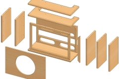
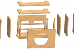
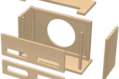
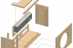
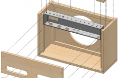
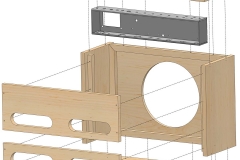
It was not until I tried to take some screenshots of exploded views and export the cut list that I found that I had made some mistakes in the model. The first mistake was that by creating a multi-body part instead of an assembly, I could not make any exploded views. I tried to automatically save the bodies as separate parts and an assembly. It was all working smoothly until I got a look at the individual parts.
I had mirrored both features and bodies throughout the model and had several incomplete pieces. Together they had all the features the part needed, but none of them had all of the features. I could try to go back through the model and redo any solid body mirrors, but I would also need to redefine a lot of geometry in the sketches to account for faces reorienting and being replaced.
Reworking the model would take a good amount of time, so I decided to simply start fresh.
Restarting
Because my first model didn’t end up as polished as it seemed I was extra careful starting my next model. I actually started a couple that I later abandoned. The one I chose to move forward one has, so far, turned out to be the properly mated and linked assembly I was hoping for.
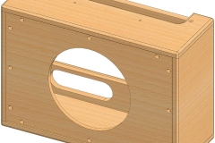
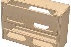
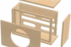
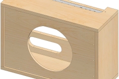
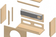
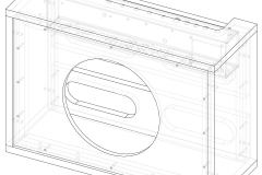
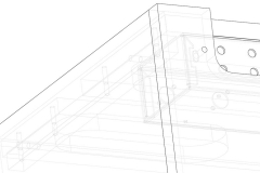
I built this updated model as an assembly. I inserted new parts and edited the geometry within the assembly. This gave me the flexibility I liked from the previous multi-body model I made, but also kept each solid body separated more completely.
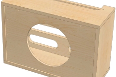
The model includes the holes for the dowels that will be used to secure the corners and all of the baffle mounts. The dowels are not included. All of the screw hols for the baffles are included as well.
Finishing What I Started
With so much progress made on my cabinet model I was fired up to try to fix and finish my chassis model. When I opened it up I realized I had started the model in metric measurements, while my cabinet model was imperial. Not wanting to do all the conversions I moved forward and would have mixed measurements in the assembly. It ultimately won’t make much difference since I only need to ensure that two holes line up between the cabinet model and the chassis model.
I had gotten much better at aligning my sketch planes and geometry to existing features while modeling the cabinet. When I took a look at my chassis model I immediately noticed some issues that I had not seen in the past.
The problems were mainly in the corners where some flanges were not properly defined. When I last worked on this model I was trying to leave some allowances at the corners for the bending material. I could now redraw the sketches controlling the added flange and the cutouts much more effectively.
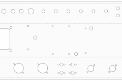
I was able to make quick work of finishing out the small flanges that would be welded to the top control surface and bottom tube face once they were bent into place. Now I had to finish laying out the mounting holes and cutouts in the chassis.
The model was left with the tube socket and power transformer cutouts completed. All that was left was to lay out the rest of the holes and do an extruded cut.
Assembling the Assemblies
Finally, I have all the pieces modeled and ready to put into a complete assembly. Rather than importing the chassis as a part to the cabinet model, I decided to create a new assembly and import the cabinet assembly model as a subassembly. My thinking is that I can keep things a little more modular in case I want to reuse the cabinet model with another chassis or otherwise reuse the models in different configurations.
Aligning the chassis to the cabinet took all of three mates. The chassis was centered in the cabinet, then the control panel was mated to the bottom face of the top piece of the cabinet. Finally, the open part of the chassis was mated with the inside face of the top back baffle.
When I created the cabinet model I did not reference the chassis model for the geometry of the cabinet top cutout. With the chassis in place, I edited the cutout of the top so the mounting holes on the amp aligned with the center of the mounting slots on the chassis. Then I adjusted the cutout for the control panel, making sure to leave clearance for everything that would be mounted to the panel.
Next Steps
The model is pretty well finalized, the only things missing right now are the dowel pins for all the joints and the holes for the carry handle.
Before I cut into any of the wood I have for this, I want to make sure everything will fit. I plan to do some simple models of everything that will be outside of the chassis, namely the tubes and sockets, transformers, choke, and capacitor bank. I also want to select a speaker and create a rough model to make sure there is clearance between the chassis and speaker magnet.
One last thing I plan to do is to select and purchase the fabric to be used with the amp. I plan to cover the cabinet in a tweed or similar fabric. I have not decided for a color or material for the grillcloth yet. Once I get the fabric in hand I can measure and make sure I’m allowing the proper clearance. Currently I have left 1/16″ clearance between the edges of the speaker baffle and the sides, and the same clearance between the edges of the chassis and the sides.


