I Have a Dream
…of one day playing a show with all gear that I made. Guitar, amp, pedals, all of it made my me. I don’t plan to all the way, I’ll be buying the potentiometers and caps and probably most of the hardware. I do, however, plan to make the pickups.
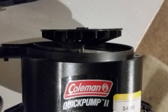
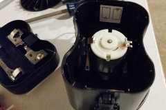
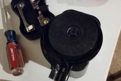
I’m also going to make the machine to wind the pickups. That’s what I’ve been poking at lately. As of now I have a very basic PWM based speed control for a brushed DC motor. I scavenged the motor from an air bed pump I got at Goodwill. It was a couple bucks and has a good basis for everything I’ll need to get up and running.
Getting Started
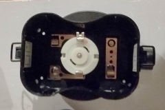
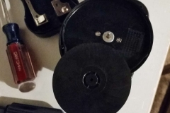
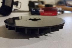
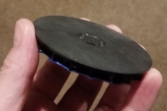
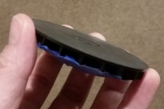
The housing is built to hold 4 D-cell batteries. I won’t be running the motor off of batteries, so I can use the entire cavity as a ready made enclosure. What’s better, the enclosure already has the mounting holes for the motor. EVEN BETTER is the fact that the impeller for the centrifugal pump is smooth on the back side. I’ve been able to take off the impeller and install it with the smooth face out, which makes for an easy mounting surface.
I’m using a low cost Arduino variant, the Digispark Pro, to run the PWM and monitor the control pot. I got two of these from their kickstarter and have never put them to use. They’re so small, though, that I think it’s a good option to squeeze into the existing housing.Getting the Digispark set up took some time. I was setting it up in Linux, which I am still getting a good hold of, and the documentation had some holes in it. Ultimately getting Micronucleus configured correctly fixed the problem. I’m working to get the process documented, but that will come later.
Where are we now, now?
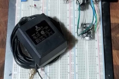
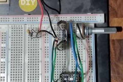
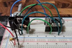
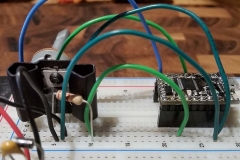
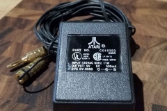
Currently I have basic open loop speed control of the DC motor. I’m using PWM to trigger a darlington transistor to switch the power from a basic wall-wart transformer outputting 9VAC. I’m using a potentiometer as a voltage divider and measuring the level to control the speed. While the setup is working, it leaves a lot to be desired.
First and foremost I will be tuning the PWM frequency and duty cycle range to try to improve the speed control of the motor. The default PWM frequency is around 400 Hz, right in the audible range, and it results in a buzzing and clicking as the duty cycle increases. Changing the settings will require going a step past the basic Arduino code to set the registers of the microcontroller directly. The relevant registers are TCCR1n.
Knowing which registers to edit, unfortunately, is not enough. I’m feeling my way through this and I’m not sure exactly what is happening to the waveform when I’m setting the registers. I need to hook up to an oscilloscope before I can really get things dialed in. There is a noticable difference when changing these settings, but it’s impossible to quantify.
Fortunately I have acccess to a ‘scope at the makerspace I use. I just need to head over and spend some time getting familiar with the performance characteristics of the output.
Looking ahead
The current circuitry is not going to cut it in the long run. I’ll be reworking the circuitry for an H-bridge for full forward and reverse speed control. The H-bridge will bring in a number of other useful features that might be fun in the future. Of course this will also require some code updates to handle rotation direction.
After the H-bridge, I’ll be looking at adding speed measurement. This will likely use either an IR sensor or a HESS sensor. This will be a major development task, but will again open a lot of doors going forward.
Project Info
As a matter of bookkeeping I’ll also need to flesh out some of the documentation. First up on the list will be a schematic. I’ll need to create the DigiSpark in Eagle to get everything hooked up properly, so that will have to wait for the next post.
I’m also working on basic setup and operation instructions in case anyone needs this in the future. Or, more likely, I need to look back at what is happening behind the scenes. Source files and documentation are available on GitHub. A first for a personal project, I’m enjoying the flexibility and easy tracking.
Check out the project files here.
Current Code Section
The code as it existed when I wrote this post. Check the project repo on GitHub for the most current version.
/*
Pickup winder control software
Working:
- High frequency (PWM 64kHz) speed control
 - Configure Timer/Counter1 registers via TCCR1A and TCCR1B bit shift commands.
 - (False lead)Set MS_TIMER_TICK_EVERY_X_CYCLES in /home/remy/.arduino15/packages/digistump/hardware/avr/1.6.7/cores/tiny/wiring.c
- Single Darlington transistor control
- Open loop speed set by potentionmeter
Pending:
- H-bridge control
- Isolation
- Pulse counter
- RPM calculation
- RPM PID control
*/


int motorPin = 1; //Output to Darlington gate
int controlPin = 3; //Input from control pot wiper, physical pin 9 = analog 3

void setup()
{
 pinMode(motorPin, OUTPUT); //
 pinMode(controlPin, INPUT);

 #define TIMER_TO_USE_FOR_MILLIS = 0; //Use timer 0 because timer 1 configured for fast PWM
// TCCR1B = (TCCR1B & 0b11111000) | 0x01;
// TCCR1B = TCCR1B & B11111000 | B00000001;
//
// //Configure TCCR1 registers for Fast PWM with TOP=OCR1A, freq prescale 1
// TCCR1A = _BV(WGM11) | _BV(WGM10);
// TCCR1B = _BV(WGM13) | _BV(WGM12) | _BV(CS10);

 //Configure TCCR1 registers for Fast PWM with TOP=0x00FF (255), freq prescale 1
 TCCR1A |= _BV(COM1A1) | _BV(COM1A0) | _BV(WGM10); //| _BV(WGM11) | _BV(COM1A1) | _BV(COM1A0) |
 TCCR1B |= _BV(WGM12) | _BV(CS10); //_BV(WGM13) | _BV(CS11) |

}


void loop()
{
 int speed = analogRead(controlPin);
 speed = speed/4;

 if (speed >= 0 && speed <= 255)
 {
 analogWrite(motorPin, speed);
 }

////Analog Input test
// int test = analogRead(3);
// if (test > 512)
// {
// digitalWrite(motorPin, HIGH);
// }
// else
// {
// digitalWrite(motorPin, LOW);
// }

//PWM test
// analogWrite(motorPin, 100);
// delay(2000);
// analogWrite(motorPin, 0);
// delay(3000);
// analogWrite(motorPin, 200);
// delay(5000);
// analogWrite(motorPin, 0);
// delay(1000);

}


