Tag Archives: Electronics

Pickup Winder DC Motor Control Prototyping

I Have a Dream

…of one day playing a show with all gear that I made. Guitar, amp, pedals, all of it made my me. I don’t plan to all the way, I’ll be buying the potentiometers and caps and probably most of the hardware. I do, however, plan to make the pickups.

I’m also going to make the machine to wind the pickups. That’s what I’ve been poking at lately. As of now I have a very basic PWM based speed control for a brushed DC motor. I scavenged the motor from an air bed pump I got at Goodwill. It was a couple bucks and has a good basis for everything I’ll need to get up and running.

Continue reading Pickup Winder DC Motor Control Prototyping

Prototype Boost Built, Testing to Come

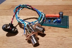
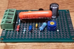
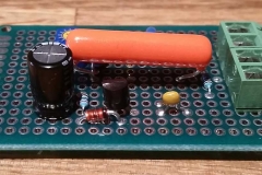
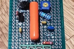
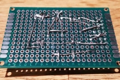
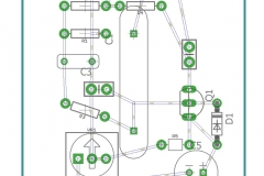
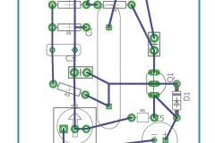
Building on my work from a couple weeks ago, I put solder to iron and built up a first prototype of the boost circuit for my buddy’s 8-bit fuzz pedal. Th EagleCAD board layout I made earlier was almost exactly what I needed. However, because I was fumbling my way through the software I didn’t have the correct packages selected for all of the devices.

I tweaked the layout with the actual components I ordered from Digikey a few weeks ago. The biggest curveball was that I ordered some gigantic orange 1000pF caps. I just wasn’t looking that closely at packages when I ordered, but I had plenty of board to work with.

I hooked up some 1/4″ jacks to the I/O terminals and connected a 9V. I tested with my Epiphone Les Paul into a Focusrite Scarlet interface. The signal came through clear and clean, and there was no audible (to me at least) distortion as I rolled through the gain range. 

I’ll take the board over to check out the performance characteristics on an oscilloscope soon. Then, I’ll start looking to shrink the footprint of the board as much as possible so I can cram it inside an existing pedal.

Planning and Prototyping a Mosfet Boost Circuit

Long ago I promised my friend Nick a mod for a guitar pedal of his. His 8-bit fuzz pedal caused a volume drop that he couldn’t overcome by tweaking the settings, and he didn’t want to put a boost after because he would have to hit two pedals every time he wanted to switch to his fuzz. I had been looking at making a couple of different boost circuits and offered to put one in his pedal.

Now, some years later, I’m actually putting some effort into the project. The circuit I chose is the Mosfet Booster pedal from AMZ .  The circuit was simple and would make for a very transparent gain stage. The idea is to make a small add-on board for his current pedal and wire the boost in line before the output jack.

I had seen a Hack-a-Day series about creating PCB’s in a number of different software, in particular a walk-through of using Eagle CAD. I’ve seen so many mentions of Eagle CAD over the years, but never used it. This simple circuit would make a good intro to the program.

Continue reading Planning and Prototyping a Mosfet Boost Circuit

Fixing a Broken Power Switch

My dad’s old record player had been out of use at my mom’s house for years because of a bad power button. He had good taste in AV equipment and I didn’t like seeing it sit unused. I offered to trade my mom a working but nothing special Technics SL-BD2 for a broken Phase Linear turntable.

I started testing things out and found a problem very quickly. The power button was sticky at best, and never seemed to click and move. The action should have been similar to a click top pen, but there was hardly any movement.

Getting to the switch was a pain. I had to take the turntable completely apart to get into the switch. Outwardly there did not seem to be anything wrong with it, but clicking it directly I felt the same resistance as when it was installed. It wasn’t the button cap causing the problem, there was definitely an issue with the switch itself.

Continue reading Fixing a Broken Power Switch

Bassman Amp Design – CAD Model

Motivation

The recent find of some good looking 3/4″ plywood was the swift kick I needed to get the ball rolling on a long dormant project. A few years ago I started down the road of building a Fender Bassman clone based on the 5F6 circuit. I was going to do this remotely with a friend. He would handle some electronics analysis for some mods we had in mind, and I would guide the mod selection and build the cabinet. I even went so far as to buy a chassis.

Unfortunately the project never went much further and the chassis sat in the corner of my room for a long time. Then, looking for a CAD project to practice on, I picked it up and got a sheet metal part about 80% done. It was a full box with one of the three faces completed with punched holes.

Getting Started

Knowing I had the chassis model nearly done I started to put together a model of the plywood cabinet. I’ve never had much luck modeling larger assemblies from the ground up and wanted to try something new. I had heard the term “top-down” in relation to CAD models and it seemed like the way to go.

Step one was to do a little research on Fender cabinets similar to what I had in mind. I wanted to skip the 4×10 configuration the Bassman is known for in favor of a much more portable and apartment friendly 1×12 combo. I used a few pictures and drawings of the 4×10 configuration to get an idea for the parts involved, then changed the baffle design and size to fit a single 12″ speaker.

Continue reading Bassman Amp Design – CAD Model

Pignose G40V Backlog

A few years ago my best friend Nick asked me to do some mods to his amp. He’d recently acquired this cool little brown 40w 10 inch Pignose g40v. The design was very simple and followed an old Bassman schematic pretty closely. The mods that Nick had been eyeing would bring it even closer to the Bassman. He linked me to a couple of blog posts and schematics and I made my way to HSC, a local electronic component warehouse.

The original amp has been holding up well since and has survived him gigging around Utah. When he found another on on Craigslist he made sure to scoop it up and drop it off with me for an upgrade. The second overhaul followed the first very closely, but this time I left out the standby switch and I didn’t break the presence pot and replace it with something only kind of close in value.

I took pictures with the intention of doing a full write up, and one day maybe I will, but for now this project is stuck in the backlog. Enjoy the pictures in the meantime.